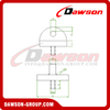
Lifting Loop with Pressure Plate & “Goliath”
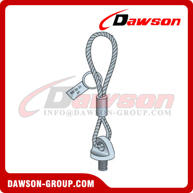
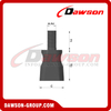
Goliath Lifting Loop with Pressure Plate
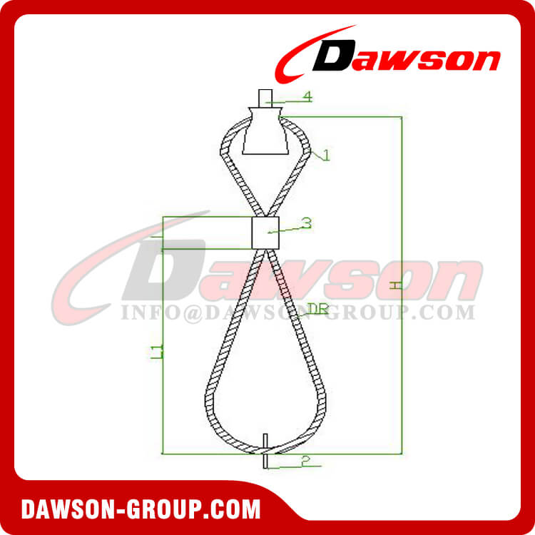
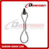
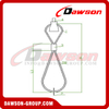
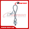
Lifting loop with pressure Plate and “Goliath” are to be used as lifting device for the lifting anchors of Threaded Lifting System (Bar Anchors, Waved Anchors DWL and DWK, Sockets, Crimped Sockets, Flat Steel Anchors)
The lifting loop eye is welded on the base plate. The retracted rope loop allows stress forces from all directions.
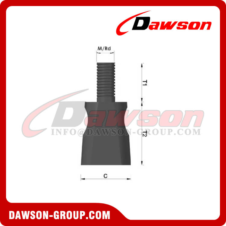
Lifting Ring Screw can be applied with the thread anchor with appropriate metric or Rd thread.
Identification label shows the size of thread and maximum working load.

Materials:
●1 Loop: Galvanized steel wire rope
●2 Label Identification: plastic or steel
●3 Al Ferrule
●4 Goliath or plate: steel
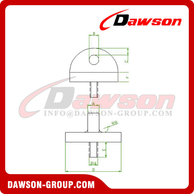
Table 3: Dimensions of the loop
| Goliath | Pressure Plate |
M/Rd
(mm) | T1
(mm) | T2
(mm) | C
(mm) | D
(mm) | A
(mm) | B
(mm) | C
(mm) | E
(mm) | F
(mm) |
| 12 | 20 | 40 | 30 | 40 | 10 | 8 | 10 | 15 | 10 |
| 16 | 22 | 40 | 33 | 40 | 10 | 10 | 10 | 15 | 10 |
| 20 | 25 | 65 | 60 | 49 | 13 | 12 | 13 | 18 | 13 |
| 24 | 30 | 65 | 55 | 56 | 14 | 16 | 14 | 24 | 14 |
| 30 | 35 | 70 | 55 | 69 | 18 | 20 | 18 | 30 | 18 |
| 36 | 35 | 120 | 90 | 79 | 20 | 24 | 20 | 36 | 20 |
| 42 | 40 | 120 | 90 | 99 | 25 | 30 | 25 | 45 | 25 |
| 52 | 40 | 120 | 100 | 109 | 28 | 36 | 28 | 55 | 28
|
1.Handing and use
● The lifting ring screws must be completely screwed into the lifting anchor threaded sockets. If necessary Dirty thread in the lifting anchor must be cleaned. It is easier to screw in the threaded bolt if this is lightly oiled before.
● The lifting ring screws should only be attached to the unit after the concrete strength has reached 15N/m ㎡.In some cases it may be economic and practical to leave the loops with the unit until final installation.
● Maximum permissible lifting angles of the loops:
● Check if there is full contact with the concrete
● Check that the radius of the hook is at least the diameter of the rope:
To achieve a better durability a hook radius of 5 times of the rope is recommended
2. Condition of Thread Lifting Loops
The condition of Thread lifting loops should be checked regularly. They can not be used in one of the following faults be detected:
● 4 ruptures of wire at the distance the length of which is equal to three diameters of wire.
● 6 ruptures of wire at the distance the length of which is equal to six diameters of wire.
● 16 ruptures of wire at the distance the length of which is equal to thirty diameters of wire.
● Braiding rupture, deformation caused by pressure.
● Bended parts or swells at the bends.
● Thread damage at the wire chuck.
● Obvious wear, corrosive damage and other visible defects.
Lifting Clutch System Show:
Other related products:
 English


 To achieve a better durability a hook radius of 5 times of the rope is recommended