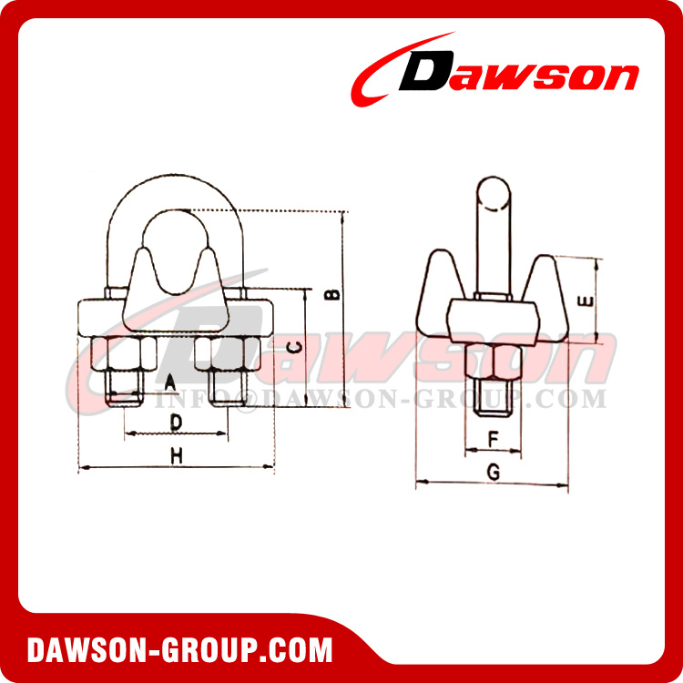
| Item No. DAWSON | SIZE(Inch) | Dimensions(Inch) | Torque In |
| A | B | C | D | E | F | G | H | Ft . Lbs |
| DG-WRC0216 | 1/8 | 0.22 | 0.72 | 0.44 | 0.47 | 0.41 | 0.35 | 0.81 | 0.94 | 4.5 |
| DG-WRC0316 | 3/16 | 0.25 | 0.97 | 0.56 | 0.59 | 0.50 | 0.44 | 0.94 | 1.16 | 7.5 |
| DG-WRC0416 | 1/4 | 0.31 | 1.03 | 0.50 | 0.75 | 0.66 | 0.56 | 1.19 | 1.44 | 15 |
| DG-WRC0516 | 5/16 | 0.38 | 1.38 | 0.75 | 0.88 | 0.72 | 0.69 | 1.31 | 1.69 | 30 |
| DG-WRC0616 | 3/8 | 0.44 | 1.50 | 0.75 | 1.00 | 0.91 | 0.75 | 1.63 | 1.94 | 45 |
| DG-WRC0716 | 7/16 | 0.50 | 1.88 | 1.00 | 1.19 | 1.03 | 0.88 | 1.81 | 2.28 | 65 |
| DG-WRC0816 | 1/2 | 0.50 | 1.88 | 1.00 | 1.19 | 1.13 | 0.88 | 1.91 | 2.28 | 65 |
| DG-WRC0916 | 9/16 | 0.56 | 2.25 | 1.25 | 1.31 | 1.22 | 0.94 | 2.06 | 2.50 | 95 |
| DG-WRC1016 | 5/8 | 0.56 | 2.38 | 1.25 | 1.31 | 1.34 | 0.94 | 2.06 | 2.50 | 95 |
| DG-WRC1216 | 3/4 | 0.62 | 2.75 | 1.44 | 1.50 | 1.41 | 1.06 | 2.25 | 2.84 | 130 |
| DG-WRC1416 | 7/8 | 0.75 | 3.12 | 1.62 | 1.75 | 1.59 | 1.25 | 2.44 | 3.16 | 225 |
| DG-WRC1616 | 1 | 0.75 | 3.50 | 1.81 | 1.88 | 1.78 | 1.25 | 2.63 | 3.47 | 225 |
| DG-WRC1816 | 1 1/8 | 0.75 | 3.88 | 2.00 | 2.00 | 1.91 | 1.25 | 2.81 | 3.59 | 225 |
| DG-WRC2016 | 1 1/4 | 0.88 | 4.25 | 2.13 | 2.31 | 2.19 | 1.44 | 3.13 | 4.13 | 360 |
| DG-WRC2216 | 1 3/8 | 0.88 | 4.63 | 2.31 | 2.38 | 2.31 | 1.44 | 3.13 | 4.19 | 360 |
| DG-WRC2416 | 1 1/2 | 0.88 | 4.94 | 2.38 | 2.59 | 2.44 | 1.44 | 3.41 | 4.44 | 360 |
| DG-WRC2616 | 1 5/8 | 1.00 | 5.31 | 2.62 | 2.75 | 2.66 | 1.63 | 3.63 | 4.75 | 430 |
| DG-WRC2816 | 1 3/4 | 1.13 | 5.75 | 2.75 | 3.06 | 2.94 | 1.81 | 3.81 | 5.28 | 590 |
| DG-WRC3216 | 2 | 1.25 | 6.44 | 3.00 | 3.38 | 3.28 | 2.00 | 4.44 | 5.88 | 750 |
| DG-WRC3616 | 2 1/4 | 1.25 | 7.13 | 3.19 | 3.88 | 3.19 | 2.00 | 4.50 | 6.38 | 750 |
| DG-WRC4016 | 2 1/2 | 1.25 | 7.69 | 3.44 | 4.13 | 3.69 | 2.00 | 4.05 | 6.63 | 750 |
| DG-WRC4416 | 2 3/4 | 1.25 | 8.31 | 3.56 | 4.38 | 4.88 | 2.00 | 5.00 | 6.88 | 750 |
| DG-WRC4816 | 3 | 1.50 | 9.19 | 3.88 | 4.75 | 4.69 | 2.38 | 5.88 | 7.63 | 1200 |
| DG-WRC5616 | 3-1/2 | 1.50 | 10.75 | 4.50 | 5.50 | 6.00 | 2.38 | 6.19 | 8.38 | 1200
|
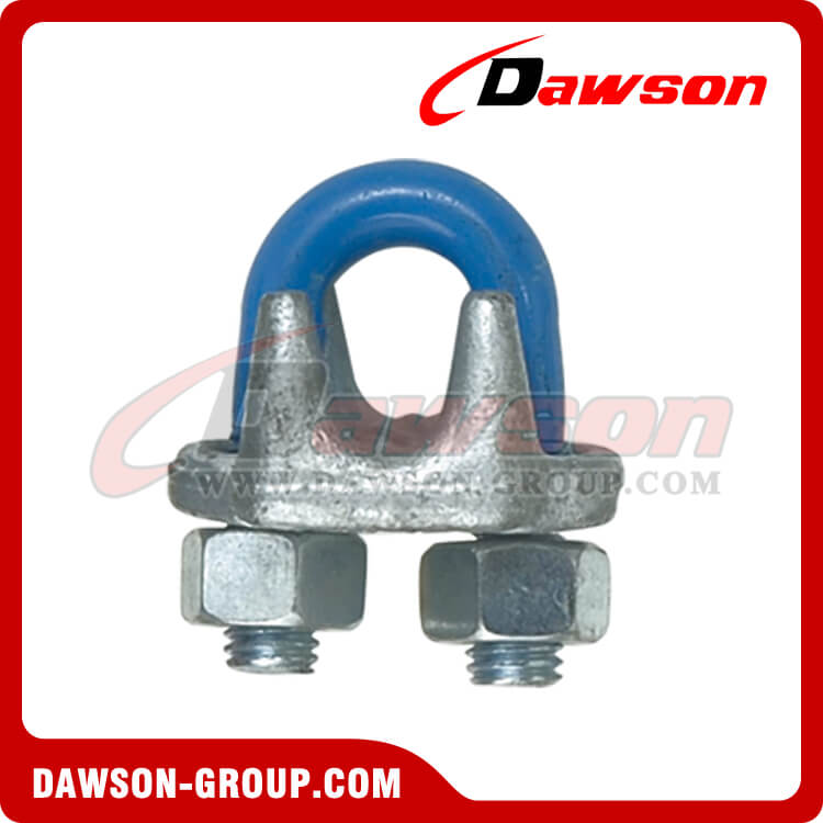
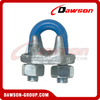
Drop Forged Steel Wire Rope Clips Type DG450, American Standard.
Material: Steel Forged.
Finish: E-Galv. or Hot Dipped Galv.(U-bolt and/or nuts for diameter bow 5, 6, 8 and 10 are electro galvanized)
Packing: In Cartons And then on Pallets.
Please take it in mind: DAWSON only supply the qualified Products.
Dawson Clips, all sizes 1/4" and larger, meet the performance requirements of Federal Specification FF-C-450 TYPE 1 CLASS 1, except for those provisions required of the contractor.
*Electro-plated U-Bolt and Nuts.
Stainless steel AISI304 or AISI316 Wire rope Clip
Malleable Cast Wire Rope Clip
Application
Wire rope clips are used on wire rope eye-loop connections or complete loops, end-to-end connections where socketing or splicing is not feasible or when a temporary joint is required.
Range
Dawson offers a wide range of wire rope clips in specifically standardized models such as EN 13411-5 and DIN wire rope clips. also offers a wide range of other wire rope clips
Design
Dawson wire rope clips are drop forged and have a bridge with grooves to tighten the wire rope properly in the clip; the DIN wire rope clips have a malleable base, without grooves.
Wire rope clips are generally marked with:
• manufacturer’s symbol - e.g. DAWSON
• wire rope diameter in mm or inches - e.g. 13 or 1/2”
• traceability code - e.g. DS21
Instructions for use
Wire rope clips should be inspected before use to ensure that:
• all markings are legible;
• a wire rope clip with the correct dimensions has been selected;
• the nuts or any other locking system cannot vibrate out of position;
• the wire rope clip is free from nicks, gouges and cracks;
• never modify, repair or reshape a wire rope clip by machining, welding, heating or bending as this may affect their performance.
The wire rope clip should be fitted to the wire rope as shown in below figures. The bridge of the wire rope clip should always be placed on the load bearing part of the rope. The U-bolt of the clip should be placed on the rope tail, also known as the dead end of the rope. Turn back enough wire rope length so that the required minimum number of clips can be installed according to the instructions below.
The first clip must be placed one bridge width from the turned-back rope tail or dead end of the rope, according to figure 1. Tighten the nuts to the specified torque.
The second clip must be placed immediately against the thimble. Take care that the correct tightening of the clip does not damage the outer wires of the wire rope (figure 2). Tighten the nuts firmly but not yet to the specified torque.
The following clips should be placed on the wire rope between the first and second clip in such a way that they are separated by at least 1½ times the clip-width with a maximum of 3 times the clip-width, according to figure 3.
Apply light tension on the rope and tighten all nuts evenly, alternating until reaching the specified torque.
After assembly and before the rope is taken into service, the nuts must be tightened further to the prescribed torque. After the load has been applied to the assembly for the first time, the torque value must be checked and corrected if necessary. Re-tightening of the nuts must be done at 10.000 cycles (heavy usage), 20.000 cycles (moderate usage) or 50.000 cycles (light usage). If cycles are unknown, a competent person could fix a time period, e.g. every 3 months, 6 months, annually.
The torque values and the minimum number of clips to be applied for a particular rope size are given in the following tables.
| diameter wire rope | diameter wire rope | min. no of clips required | length of rope to turn back | torque value | torque value |
| inch | mm |
| mm | Nm | Ft.Lbs |
| 1/8 | 3-4 | 2 | 85 | 6.1 | 4.5 |
| 3/16 | 5 | 2 | 95 | 10.2 | 7.5 |
| 1/4 | 6-7 | 2 | 120 | 20.3 | 15 |
| 5/16 | 8 | 3 | 133 | 40.7 | 30 |
| 3/8 | 9-10 | 3 | 165 | 61 | 45 |
| 7/16 | 11 | 3 | 178 | 88 | 65 |
| 1/2 | 12-13 | 3 | 292 | 88 | 65 |
| 9/16 | 14-15 | 3 | 305 | 129 | 95 |
| 5/8 | 16 | 3 | 305 | 129 | 95 |
| 3/4 | 18-20 | 4 | 460 | 176 | 130 |
| 7/8 | 22 | 4 | 480 | 305 | 225 |
| 1 | 24-26 | 5 | 660 | 305 | 225 |
| 1-1/8 | 28-30 | 6 | 860 | 305 | 225 |
| 1-1/4 | 32-34 | 7 | 1120 | 488 | 360 |
| 1-3/8 | 36 | 7 | 1120 | 488 | 360 |
| 1-1/2 | 38-40 | 8 | 1370 | 488 | 360 |
| 1-5/8 | 41-42 | 8 | 1470 | 583 | 430 |
| 1-3/4 | 44-46 | 8 | 1550 | 800 | 590 |
| 2 | 48-52 | 8 | 1800 | 1017 | 750 |
| 2-1/4 | 56-58 | 8 | 1850 | 1017 | 750 |
| 2-1/2 | 62-65 | 9 | 2130 | 1017 | 750 |
| 2-3/4 | 68-72 | 10 | 2540 | 1017 | 750 |
| 3 | 75-78 | 10 | 2690 | 1627 | 1200
|
Table 1, Dawson wire rope clips generally to EN 13411-5 Type B, required number and torque value
| diameter wire rope | min. no of clips required | Torque value | Torque value |
| mm |
| Nm | Ft.lbs |
| 5 | 3 | 2 | 1.5 |
| 6.5 | 3 | 3.5 | 2.6 |
| 8 | 4 | 6 | 4.4 |
| 10 | 4 | 9 | 6.6 |
| 12 | 4 | 20 | 14.8 |
| 13 | 4 | 33 | 24.3 |
| 14 | 4 | 33 | 24.3 |
| 16 | 4 | 49 | 36 |
| 19 | 5 | 68 | 50 |
| 22 | 5 | 107 | 79 |
| 26 | 5 | 147 | 108 |
| 30 | 6 | 212 | 156 |
| 34 | 6 | 296 | 218 |
| 40 | 6 | 363 | 268
|
Table 2, Wire rope clips generally to EN 13411-5 Type A, required number and torque value
The efficiency of a wire rope termination made with wire rope clips depends on the correct placement of the clips on the rope and on correct fitting and tightening of the clips. With inadequately tightened nuts or with an insufficient number of wire rope clips the rope end may slide through the clips during use.
The fitting of the clips on the ropes may be affected by various circumstances, such as:
• the nut may be tight on the thread, yet not tight against the bridge;
• contamination of the thread by dirt, oil or corrosion products, which may prevent correct tightening of the nut.
Forged wire rope clips provide greater bearing surface and more consistent strength than malleable cast iron clips.
Suitable applications of wire rope clips to EN 13411-5 standards include suspending static loads and single use lifting operations which have been assessed by a competent person taking into account appropriate safety factors.
Wire rope clips should not be used in following applications:
• hoist ropes in mines;
• rope drives for cranes in steel works and rolling mills;
• permanent fastening of ropes in other rope drives;
• rope terminations for load suspension devices in the operation of lifting appliances, except in the case of lifting tackles where these are produced for a special application and used only once.
Wire rope clips must be regularly inspected in accordance with the safety standards given in the country of use. This is required because the products in use may be affected by wear, misuse, overloading etc. Which may lead to deformation and alteration of the material structure. Inspection should take place at least every six months and more frequently when the products are used in severe operating conditions.
Products Show:
Other related products:
Hot Tags: galvanized wire rope clip, drop forged wire rope clip, DG450 wire rope clip, American wire rope grip, dawson brands wire rope clip, wire rope clip China supplier, wire rope clip China manufacturer, wire rope clip China factory, wire rope clip China exporter, high quality wire rope clip, low price EN 13411-5 Type B wire rope clip, wire rope clip in stock, wire rope clip OEM
Application of Wire Rope Clip:
Factory Show & Package:
 English